Loading Data into Databricks Delta Lake
You can use several solutions to load data into a Delta Lake table on Databricks.
Before continuing with one of the solutions, ensure that you have completed all of the required prerequisites in Databricks, including generating a personal access token, configuring and starting your Databricks cluster, and then locating the JDBC URL used to access the cluster.
- When using Amazon S3 as the staging location, see this Databricks article.
- When using Azure Data Lake Storage Gen2 as the staging location, see this Azure Databricks article.
- When using Google Cloud Storage as the staging location, see this Databricks article.
- Bulk load data into a
Delta Lake table
Build a pipeline that reads new Salesforce data, cleans some of the input data, and then passes the data to the Databricks Delta Lake destination. The Databricks Delta Lake destination first stages the data in an Amazon S3 staging location, and then uses the COPY command to copy the data from the staging location to a Delta Lake table.
- Merge changed data into a
Delta Lake table
Build a pipeline that processes change data capture (CDC) data using the MySQL Binary Log origin and then passes the changed data to the Databricks Delta Lake destination. The Databricks Delta Lake destination first stages the changed data in an Amazon S3 staging location, and then uses the MERGE command to merge the changed data from the staging location to a Delta Lake table.
Bulk Loading Data into a Delta Lake Table
This solution describes how to build a pipeline that bulk loads Salesforce data into a Delta Lake table on Databricks.
Let's say that you want to bulk load Salesforce account data into Databricks Delta Lake for further analysis. You'd like the pipeline to clean some of the account data before loading it into Delta Lake. When the pipeline passes the cleaned data to the Databricks Delta Lake destination, the destination first stages the data in an Amazon S3 staging location, and then uses the COPY command to copy the data from the staging location to a Delta Lake table.
- Create the pipeline and configure a Salesforce origin to read account data from Salesforce.
- Configure an Expression Evaluator processor to clean the input data.
- Configure a Databricks Delta Lake destination to stage the pipeline data in text files in Amazon S3 and then copy the staged data to the target Delta Lake table.
- Run the pipeline to move the data from Salesforce to Delta Lake.
Create the Pipeline and Configure the Salesforce Origin
Create the pipeline and then configure the Salesforce origin to read account data from Salesforce.
For more detailed information about this origin, see Salesforce origin.
-
After logging into Data Collector, click the Home icon (
 ) in
the top toolbar, and then click Create New
Pipeline.
) in
the top toolbar, and then click Create New
Pipeline.
-
Enter a title for the pipeline, such as
BulkLoadDeltaLake, and then click
Save.
An empty pipeline opens in the pipeline canvas.
-
From the pipeline creation help bar, click , as follows:
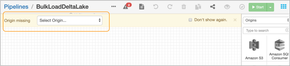
The origin is added to the canvas.
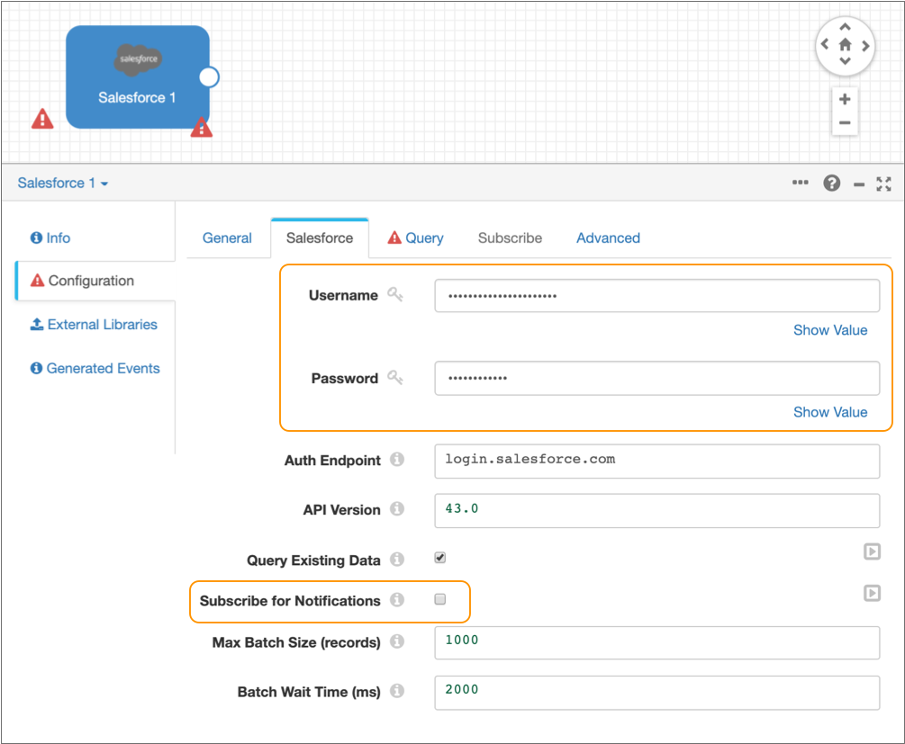
- On the Salesforce tab, enter your Salesforce user name and password.
-
Clear the Subscribe for Notifications checkbox.
This way, the origin runs a query to process existing data and is not subscribed to notifications.
-
Leave the default values for the remaining properties.
The Salesforce tab should be configured as follows:
-
Click the Query tab and enter the following query for the
SOQL Query property so that the origin reads only
these attributes from the Salesforce
accountobject:SELECT Id, Name, Type, BillingStreet, BillingCity, BillingState, BillingPostalCode, BillingCountry, ShippingStreet, ShippingCity, ShippingState, ShippingPostalCode, ShippingCountry, Phone, Fax FROM Account WHERE Id > '${OFFSET}' ORDER BY Id - Leave the default values for the remaining properties.
-
Click the error icon (
 ) in the empty pipeline canvas.
The properties panel displays the Error Records tab for the pipeline.
- Select Discard for the error records.
-
In the toolbar above the pipeline canvas, click the
Preview icon:
 .
.
When you preview the pipeline, you can verify that you correctly entered the Salesforce connection information and you can view several records of data read from Salesforce.
-
In the Preview Configuration dialog box, accept the
defaults and then click Run Preview.
If the Salesforce connection information is valid, the preview displays several records of Salesforce data, as follows:
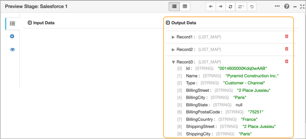
-
Click the Close Preview icon (
 )
to close the preview and continue building the pipeline.
)
to close the preview and continue building the pipeline.
Configure the Expression Evaluator Processor
Next you add and configure the Expression Evaluator processor to clean some of the account data.
The Type field contains either Customer - Direct or
Customer - Channel as the value. You'd like to clean this data
by keeping only Direct or Channel as the value
before loading the data into a Delta Lake table.
So you add an Expression Evaluator processor to the pipeline and define an expression
that uses the str:regExCapture() function to replace the value of
the Type field with only Direct or
Channel.
-
From the pipeline creation help bar, click .
The processor is added to the canvas and connected to the origin.
- Select the Expression Evaluator processor in the pipeline canvas, and then click the Expressions tab.
-
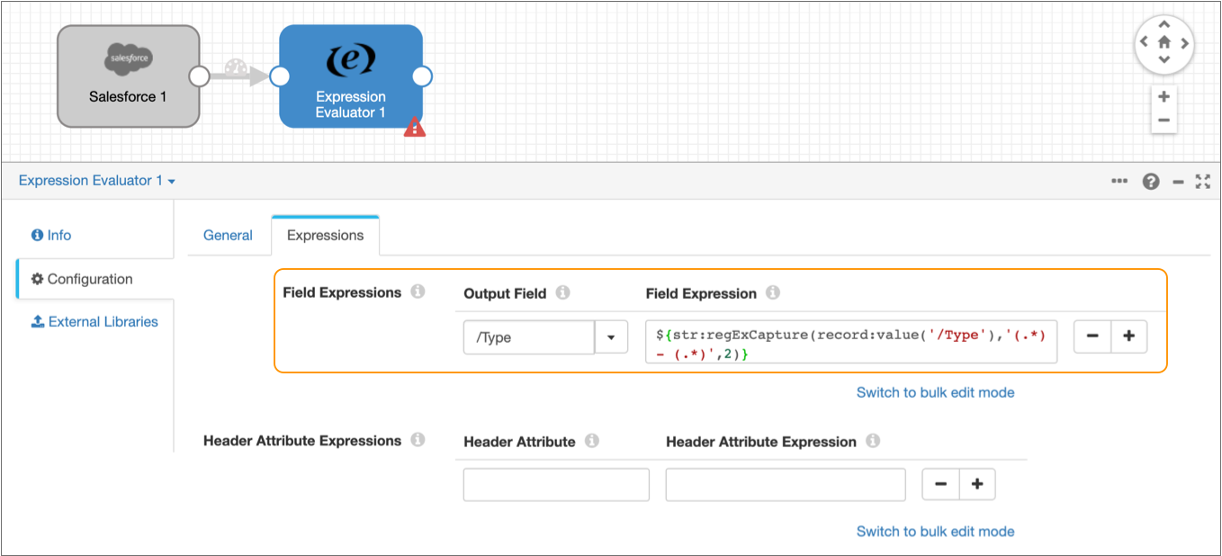
In the Field Expressions section, enter
/Type for the Output Field and
then enter the following expression for the Field
Expression:
${str:regExCapture(record:value('/Type'),'(.*) - (.*)',2)}The Expressions tab should be configured as follows:
-
To verify that the expression cleans the data as expected, click the
Preview icon () and
then click Run Preview in the dialog box.
-
When the preview starts, select the Expression Evaluator processor in the
pipeline canvas.
The preview displays the input and output data of the processor, highlighting the changed data in the
Typefield and confirming that the expression correctly removes the string Customer - from field values, as follows: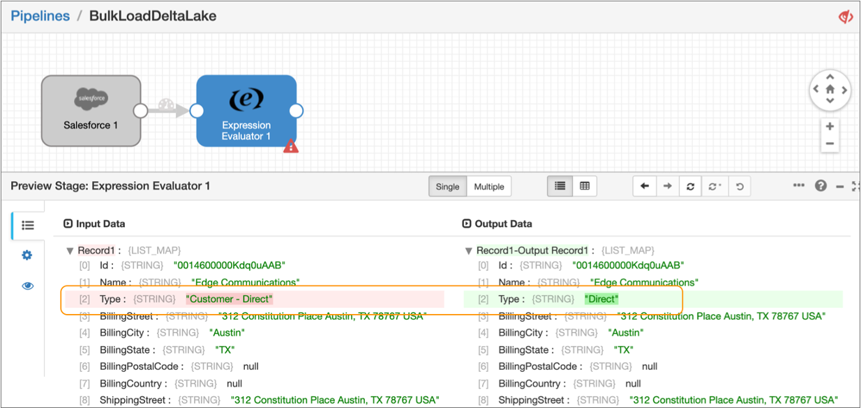
-
Click the Close Preview icon ()
to close the preview and continue configuring the next stage in the
pipeline.
Configure the Databricks Delta Lake Destination
Add and configure the Databricks Delta Lake destination to bulk load the Salesforce data into a Delta Lake table.
To bulk load data, the Databricks Delta Lake destination first stages the pipeline data in text files in Amazon S3 or Azure Data Lake Storage Gen2. Then, the destination sends the COPY command to Databricks to process the staged files.
For more detailed information about this destination, see Databricks Delta Lake destination.
-
From the pipeline creation help bar, click .
The destination is added to the canvas.
- Select the destination, and then click the Databricks Delta Lake tab.
-
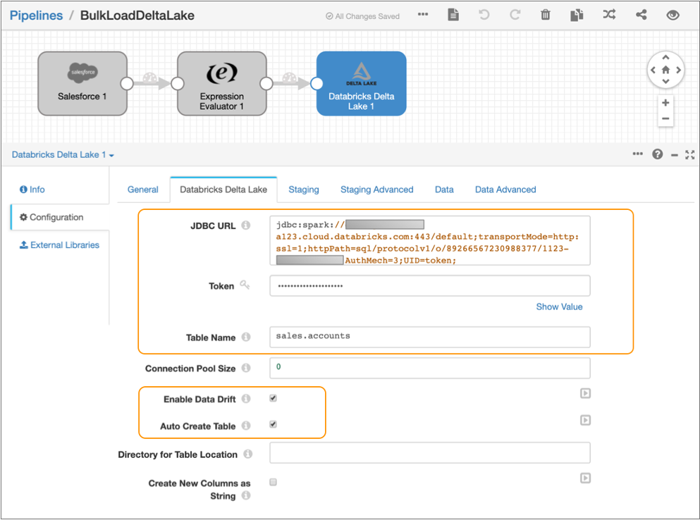
Configure the following properties:
Property Value JDBC URL Enter the JDBC URL that the destination uses to connect to the Databricks cluster. Remove the PWDparameter from the URL, and then enter the personal access token value for the Token property below.Enter in the following format:
jdbc:databricks://<server_hostname>:443/default;transportMode=http:ssl=1;httpPath=sql/protocolv1/o/0/xxxx-xxxxxx-xxxxxxxx;AuthMech=3;Token Enter the personal access token that you generated as a prerequisite in Databricks. Table Name Enter sales.accounts to write the data to the accountsDelta Lake table in thesalesdatabase.Enable Data Drift Select to compensate for data drift and automatically create new columns or tables. Auto Create Table Select to automatically create the new accounts table in Delta Lake. -
Leave the default values for the remaining properties.
The Databricks Delta Lake tab should be configured as follows:
-
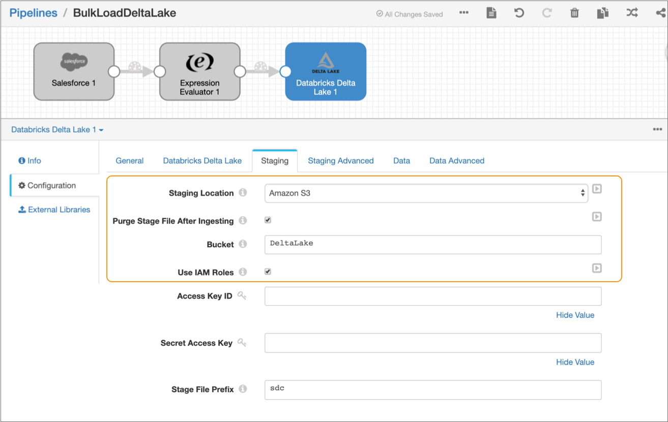
Click the Staging tab, and then set the
Staging Location to Amazon S3.
The Staging tab defines how the destination connects to the specified staging location. This solution uses Amazon S3 as the staging location and assumes that Data Collector runs on an EC2 instance with a configured instance profile. If you prefer, you can configure the destination to use an alternate staging location.
-
Configure the following properties:
Property Value Purge Stage File After Ingesting Select to enable purging a staged file after its data is successfully written to a Delta Lake table. Bucket Enter the name of the Amazon S3 bucket to write the staged files to. Use Instance Profile Select to use the instance profile assigned to the EC2 instance where Data Collector runs to connect to Amazon S3. If not using instance profiles, clear and enter your AWS secret access key pair.
-
Leave the default values for the remaining properties.
The Staging tab should be configured as follows:
Run the Pipeline
Run the pipeline to move the data from Salesforce to Delta Lake.
-
In the toolbar above the pipeline canvas, click
Start.
When the pipeline successfully starts, Data Collector displays the pipeline in Monitor mode. In Monitor mode, you can monitor the health and performance of the pipeline by viewing real-time statistics and errors as data moves through the pipeline, as displayed in the following image:
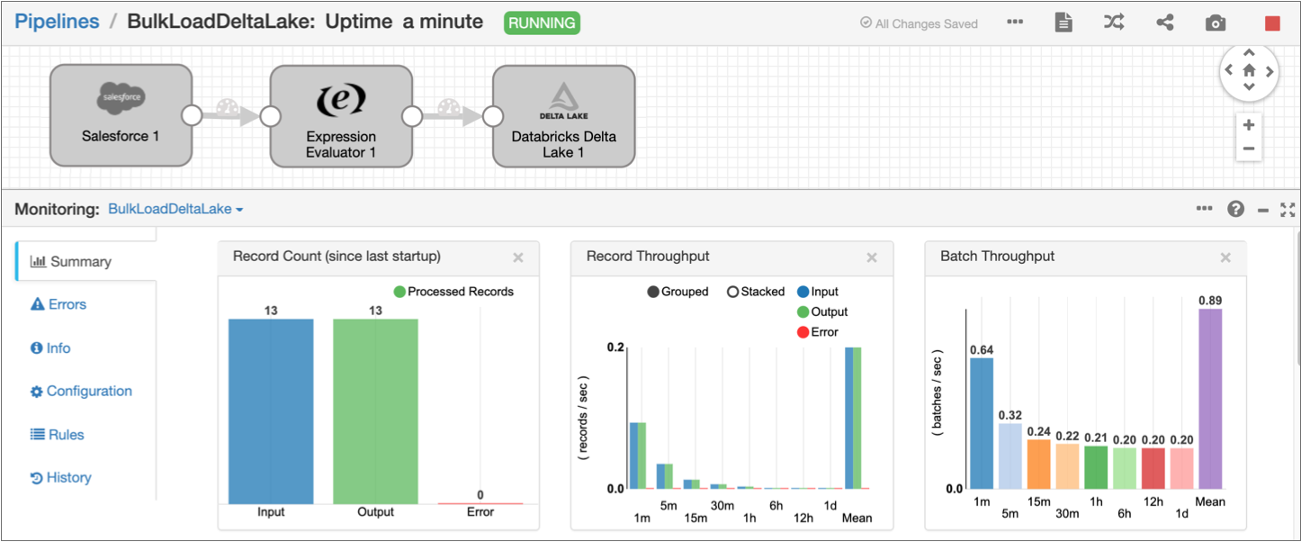
Because the Salesforce origin is configured to read all account data in bulk, the pipeline automatically stops after reading all account data.
-
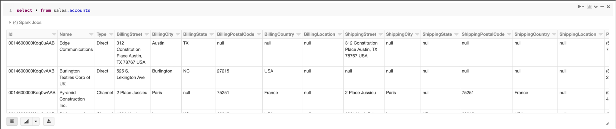
Verify that the pipeline loaded data into the Delta Lake table by running a SQL
query in your Databricks notebook.
For example, if you run the following SQL query:
select * from sales.accountsDatabricks displays the following results:
Merging Changed Data into a Delta Lake Table
This solution describes how to design a pipeline that reads change data capture (CDC) data from a database and replicates the changes to a Delta Lake table on Databricks.
Let's say that you want to track customer transactions in a MySQL table and apply those changes to a Delta Lake table for further analysis. That is, you need to apply the same set of updates, deletes, and inserts made to the MySQL table to the Delta Lake table. You first design and run a pipeline to bulk load the initial set of transactions in the MySQL table into the Delta Lake table. Then you design the CDC pipeline that processes subsequent changes.
In the CDC pipeline, you use a MySQL Binary Log origin to capture the changes from the MySQL source database. Due to the structure of the MySQL binary log records, you need to add processors to the pipeline to restructure the record and keep only the necessary fields. When the pipeline passes the data to the Databricks Delta Lake destination, the destination first stages the changed data in an Amazon S3 staging location, and then uses the MERGE command to merge the changed data from the staging location to a Delta Lake table.
- Create the pipeline and configure a MySQL Binary Log origin to read CDC information provided by MySQL in binary logs.
- Configure several processors to restructure the record based on the type of operation performed: INSERT, UPDATE, or DELETE.
- Configure a Databricks Delta Lake destination to stage the changed data in text files in Amazon S3 and then merge the staged data to the target Delta Lake table.
- Run the pipeline to replicate data from MySQL binary logs to the Delta Lake target table.
Create the Pipeline and Configure the MySQL Binary Log Origin
Create the pipeline and then configure the MySQL Binary Log origin to read CDC information provided by MySQL in binary logs.
-
After logging into Data Collector, click the Home icon () in
the top toolbar, and then click Create New
Pipeline.
-
Enter a title for the pipeline, such as CDCDeltaLake,
and then click Save.
An empty pipeline opens in the pipeline canvas.
-
From the pipeline creation help bar, click , as follows:
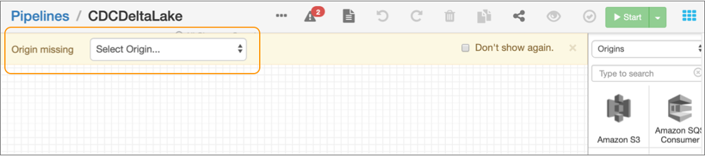
The origin is added to the canvas.
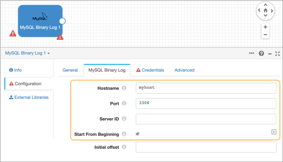
- On the MySQL Binary Log tab, enter the MySQL server host name and port number.
-
Optionally enter the replication server ID that the origin uses to connect to
the source MySQL server.
This solution assumes that the MySQL database is enabled for GTID which does not require that you configure the server ID.
- Select Start from Beginning.
-
Leave the default values for the remaining properties.
The MySQL Binary Log tab should be configured as follows:
- Click the Credentials tab and enter the user name and password to connect to MySQL.
-
Click the error icon () in the empty pipeline canvas.
The properties panel displays the Error Records tab for the pipeline.
- Select Discard for the error records.
-
In the toolbar above the pipeline canvas, click the
Preview icon: .
When you preview the pipeline, you can verify that you correctly entered the MySQL connection information, and you can view several records of data read from the binary logs.
-
In the Preview Configuration dialog box, accept the
defaults and then click Run Preview.
If the MySQL connection information is valid and if the binary log contains pending transactions, the preview displays the pending transactions, as follows:
-
Click the Close Preview icon ()
to close the preview and continue building the pipeline.
Configure Processors to Restructure the Record
Due to the structure of the MySQL binary log records, you need to add several processors to the pipeline to restructure the record and keep only the necessary fields.
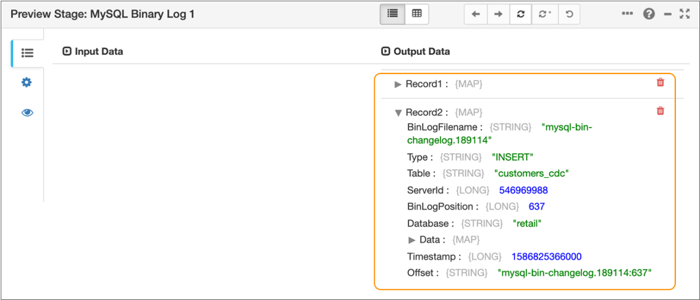
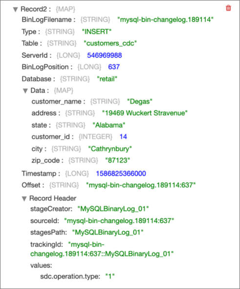
Each record generated by the MySQL Binary Log origin includes the following information:
- CRUD operation type in the
Typefield: INSERT, UPDATE, or DELETE. - Change data capture information such as the table, server ID, and timestamp in various fields.
-
New data to be inserted or updated in the
Datamap field. - Old data to be deleted in the
OldDatamap field.
For example, the origin might generate the following record for data that needs to be inserted:
You need to restructure the records differently, based on the operation type. You add
a Stream Selector processor to the pipeline to route records with a DELETE operation
in the Type field to one processing stream and to route records
with an INSERT or UPDATE operation in the Type field to another
processing stream. Then for each stream, you add a Field Remover processor to keep
only the necessary fields and a Field Flattener processor to flatten the fields in
the Data or OldData map fields.
-
From the pipeline creation help bar, click .
The processor is added to the canvas.
- Select the Stream Selector processor in the pipeline canvas, and then click the Conditions tab.
-
Click the Add icon (
 ) to add a condition.
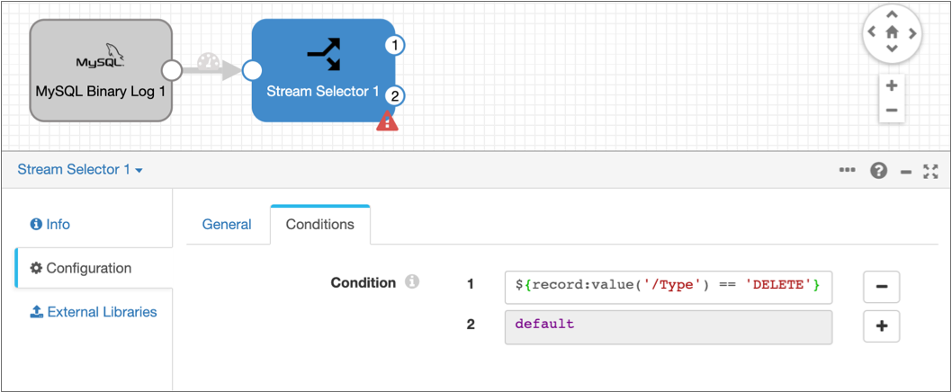
-
Enter the following expression for the condition:
${record:value('/Type') == 'DELETE'}This condition uses the StreamSets expression language to route records with a DELETE operation in the
Typefield to the first output stream of the processor. All other records, with an INSERT or UPDATE operation in theTypefield, route to the default output stream.The configured Conditions tab and the pipeline should look like this. Note that the Stream Selector processor has two output streams:
- Add a Field Remover processor, and connect the first output stream of the Stream Selector processor to the new processor.
- Select the Field Remover processor in the pipeline canvas, and then on the General tab, enter Keep OldData Fields to DELETE for the processor name.
- Click the Remove/Keep tab.
-
For Action, select Keep Listed
Fields, and then enter the following field paths for the
Fields property:
- /OldData
- /Type
This configuration keeps only the
OldDataandTypefields for records with a DELETE operation, and removes all other fields. The pipeline and the configured Remove/Keep tab should look like this: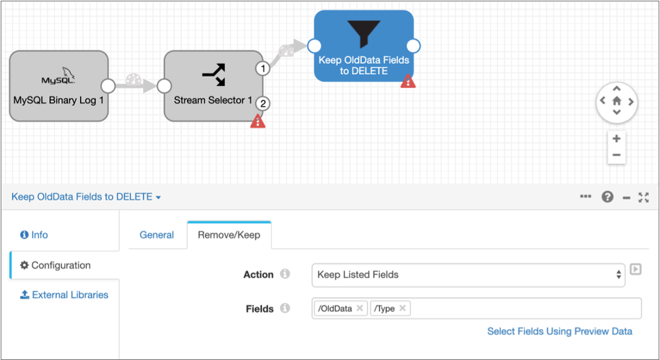
-
Select the Stream Selector processor in the pipeline canvas, and then add
another Field Remover processor.
The processor is added to the canvas, connected to the second output stream of the Stream Selector processor.
- Select the second Field Remover processor in the pipeline canvas, and then on the General tab, enter Keep Data Fields to INSERT/UPDATE for the processor name.
- Click the Remove/Keep tab.
-
For Action, select Keep Listed
Fields, and then enter the following field paths for the
Fields property:
- /Data
- /Type
This configuration keeps only the
DataandTypefields for records with an INSERT or UPDATE operation, and removes all other fields. The configured Remove/Keep tab and the pipeline should look like this: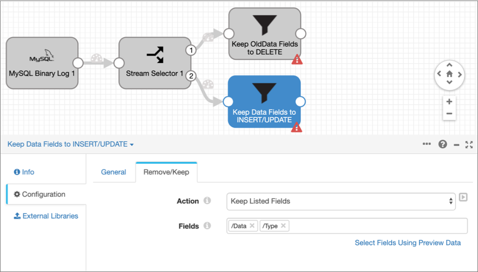
- Add two Field Flattener processors to the pipeline, connecting each to one of the Field Remover processors.
-
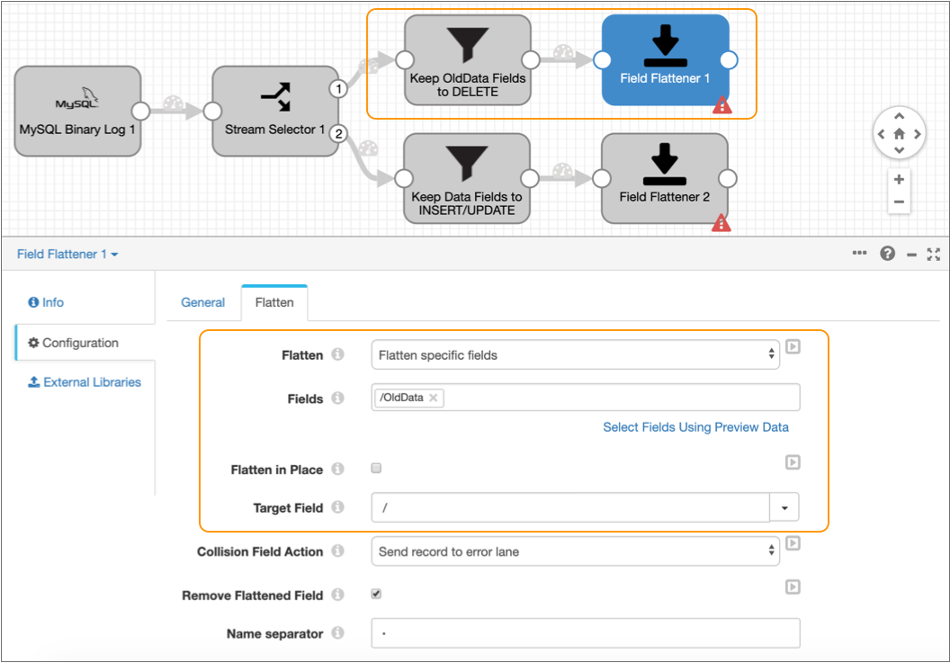
Select the Field Flattener processor in the stream that keeps the
OldDatafield, and then click the Flatten tab. -
Configure the following properties with the required values:
Property Value Flatten Select Flatten specific fields. Fields Enter /OldData. Flatten in Place Clear the property. Target Field Enter / to write the flattened data to the root field. -
Leave the default values for the remaining properties.
The Flatten tab should be configured as follows:
-
Select the second Field Flattener processor in the stream that keeps the
Datafield, and then configure it the same way as the first Field Flattener processor, except enter /Data for the Fields property. -
To verify that you've restructured the data as expected, click the
Preview icon () and
then click Confirm in the dialog box.
-
Assuming that the binary log contains pending insert or update transactions,
select the Field Remover processor that keeps the
Datafield.The preview displays the input and output data of the processor, highlighting that only the
DataandTypefields are included in the output, as follows: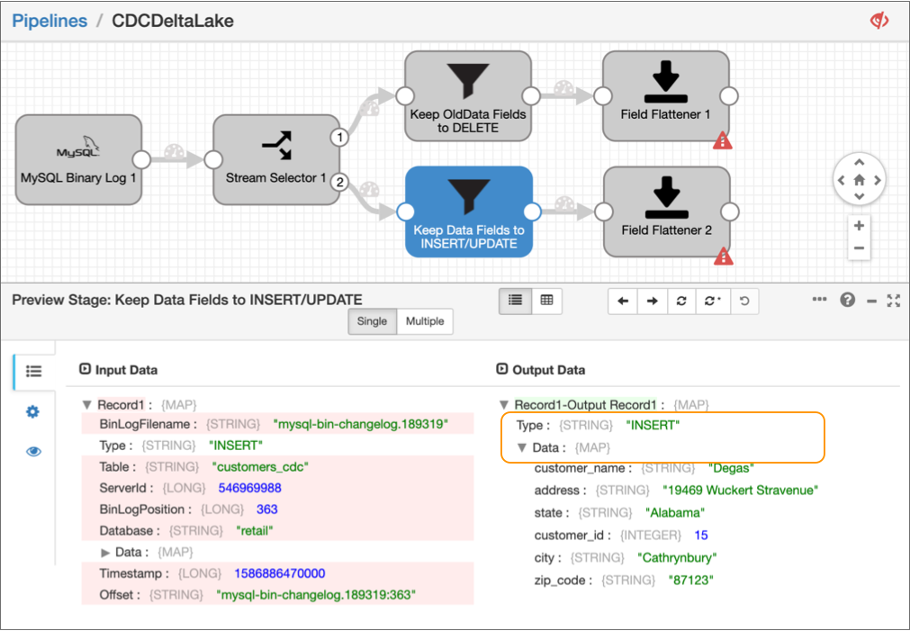
-
Next, select the Field Flattener processor connected to this Field Remover
processor.
The preview displays the input and output data of the Field Flattener processor, showing that the fields in the
Datamap field have been flattened to the root field, as follows: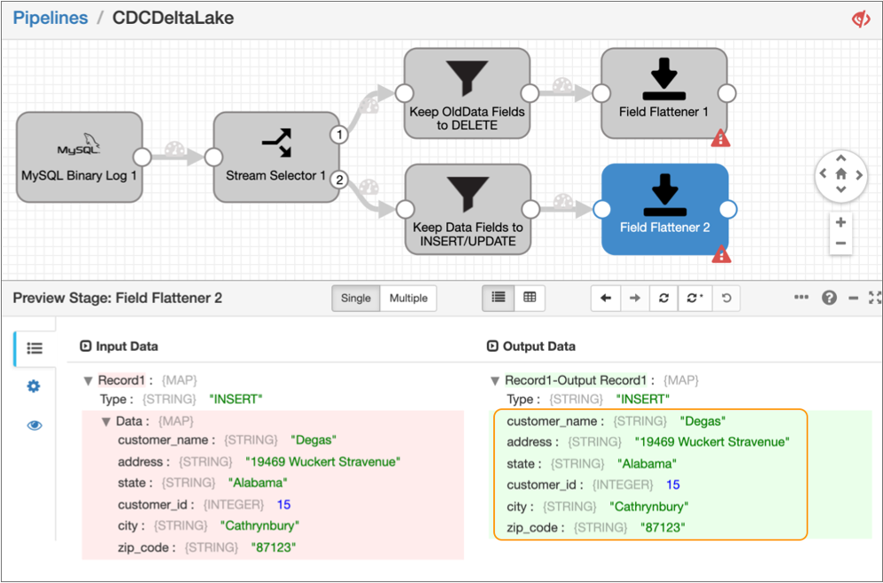
-
Click the Close Preview icon ()
to close the preview and continue configuring the next stage in the
pipeline.
Configure the Databricks Delta Lake Destination
Add and configure the Databricks Delta Lake destination to merge the changed data to a Delta Lake table.
To merge changed data, the Databricks Delta Lake destination first stages the pipeline data in text files in Amazon S3 or Azure Data Lake Storage Gen2. Then, the destination runs the COPY command to load the data to a temporary Delta Lake table, and then finally runs a MERGE command that uses the temporary table to merge the changed data into the target Delta Lake table.
For more detailed information about this destination, see Databricks Delta Lake destination.
-
From the pipeline creation help bar, click .
The destination is added to the canvas.
- Use your cursor to connect both Field Flattener processors to the destination.
- Select the destination, and then click the Databricks Delta Lake tab.
-
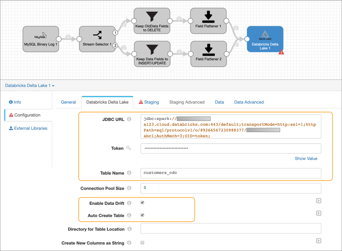
Configure the following properties:
Property Value JDBC URL Enter the JDBC URL that the destination uses to connect to the Databricks cluster. Remove the PWDparameter from the URL, and then enter the personal access token value for the Token property below.Enter in the following format:
jdbc:databricks://<server_hostname>:443/default;transportMode=http:ssl=1;httpPath=sql/protocolv1/o/0/xxxx-xxxxxx-xxxxxxxx;AuthMech=3;Token Enter the personal access token that you generated as a prerequisite in Databricks. Table Name Enter customers_cdc to write the changed data to a customers_cdctable in the defaultdeltadatabase.Enable Data Drift Select to compensate for data drift and automatically create new columns or tables. Auto Create Table Select so that the destination can automatically create the new customers_cdc table in Delta Lake. -
Leave the default values for the remaining properties.
The Databricks Delta Lake tab should be configured as follows:
-
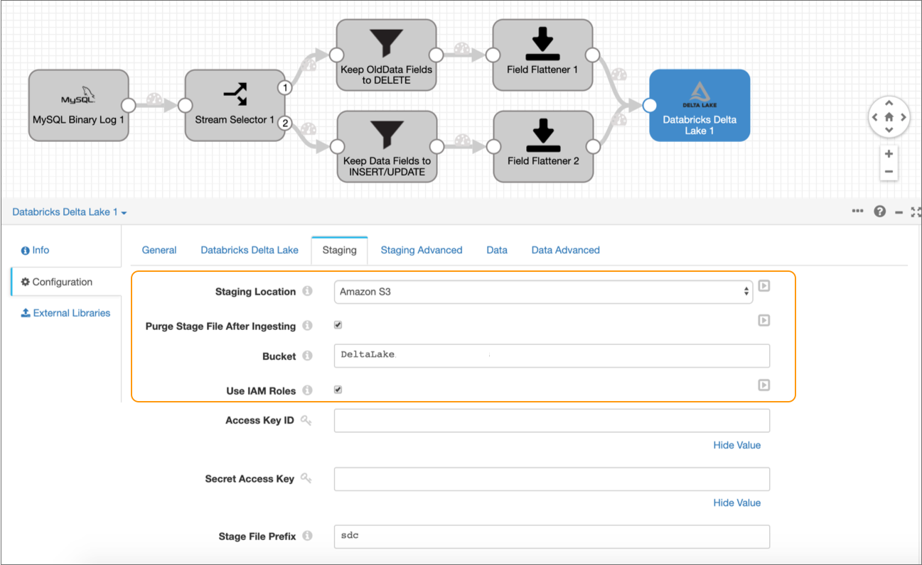
Click the Staging tab, and then set the
Staging Location to Amazon S3.
The Staging tab defines how the destination connects to the specified staging location. This solution uses Amazon S3 as the staging location and assumes that Data Collector runs on an EC2 instance with a configured instance profile. If you prefer, you can configure the destination to use an alternate staging location.
-
Configure the following properties:
Property Value Purge Stage File After Ingesting Select to enable purging a staged file after its data is successfully written to a Delta Lake table. Bucket Enter the name of the Amazon S3 bucket to write the staged files to. Use Instance Profile Select to use the instance profile assigned to the EC2 instance where Data Collector runs to connect to Amazon S3. If not using instance profiles, clear and enter your AWS secret access key pair.
-
Leave the default values for the remaining properties.
The Staging tab should be configured as follows:
- Click the Data tab.
-
Select Merge CDC Data.
Enabling this property configures the destination to use the MERGE command to insert, update, or delete the changed data in Delta Lake tables as appropriate.
-
Configure the following properties for the Key Columns
section.
The destination uses the key columns to evaluate the MERGE condition.
The Data tab should be configured as follows:Property Value Table Enter customers_cdc. Key Columns Enter customer_id. 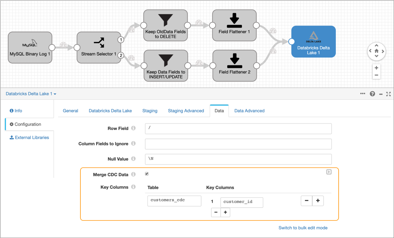
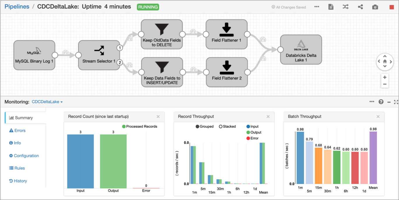
Run the Pipeline
Run the pipeline to move the changed data from MySQL binary logs to Delta Lake.
-
In the toolbar above the pipeline canvas, click
Start.
When the pipeline successfully starts, Data Collector displays the pipeline in Monitor mode. In Monitor mode, you can monitor the health and performance of the pipeline by viewing real-time statistics and errors as data moves through the pipeline, as displayed in the following image:
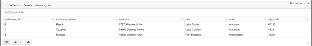
-
Next, verify that the pipeline loaded the data into the target table in Delta
Lake by running a SQL query in your Databricks notebook.
For example, if you run the following SQL query:
select * from customers_cdcDatabricks displays the following results:
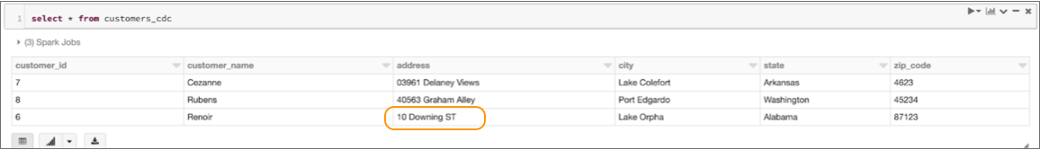
-
Verify that the pipeline successfully applies update operations to the Delta
Lake table by running the following command on the MySQL database to update one
of the rows:
update retail.customers_cdc set address='10 Downing ST' where customer_id=6;Then in your Databricks notebook, verify that the Delta Lake table has been updated with the changed address for that customer ID:
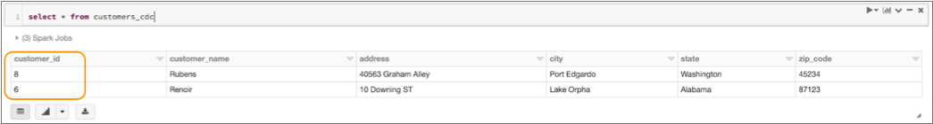
-
Verify that the pipeline successfully applies delete operations to the Delta
Lake table by running the following command on the MySQL database to delete one
of the rows:
delete from retail.customers_cdc where customer_id=7;Then in your Databricks notebook, verify that the row for that customer ID has been deleted from the Delta Lake table:
-
Click the Stop icon (
 ) to
stop the pipeline.
) to
stop the pipeline.